Crossfire 3D Printed Quadcopter Part 6
Crossfire 3D Printed Quadcopter Part 6
Mar 24, 2017
Cory Oliver
Well, we've had to take a bit of a detour over the past few weeks to get our 3D printer working again after the extruder failed. Since this blog is to document the entire process, including all the pitfalls along the way and all the things we learned, here is how we worked through it.
For whatever reason, we had 2 components on our 3D printer fail at or around the same time. The first was the RUMBA board, which is what controls the stepper motors that drive the X, Y and Z axes as well as the extruder. The second was the hot end, which stopped heating up due to a failed resistor.
The first thing I dealt with was the RUMBA board. Our printer is under warranty, so they sent us a new board, and it was a relatively easy switch. There are quite a few connections to the RUMBA, so I took a picture before removing the old one.

Replacement RUMBA board before install. Not that the new board does not come with motor drivers, of which there are 4. (one for each motor) They are easy to remove and plug right into the new RUMBA
Once we got the X/Y/Z motion working again, it was on to the problem of the extruder nozzle (known as the "hot end") not heating up. I wasn't sure if the problem was the hot end itself, or some other problem. The temperature sensor was working, and was showing the correct temperature. I unplugged the heater leads and confirmed that there was voltage going to the hot end, so that had to be the problem.

Multimeter showing 14.5 volts going to the hot end
Since now I know where the problem lies, I had to figure out how these extruders work, being that this is all new to me. It turns out they are very simple devices. A hollow nozzle made of brass, with a milled aluminum block to conduct heat, and a 6.8 ohm resistor that does the actual heating. A 100k ohm thermistor provides the temperature measurement. It's all held together with some sort of high temperature putty and kapton tape.

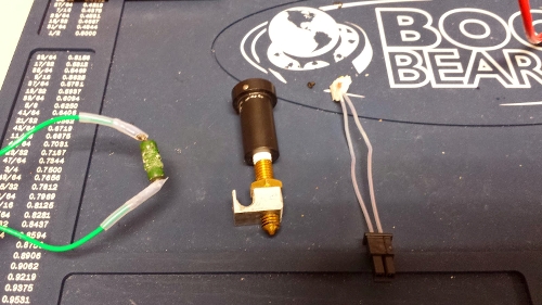
The "J-style" hot end used in the Type A Machines series 1. The green resistor is what failed, it normally sits in the groove in the aluminum block, heating up the brass components and melting the filament.
Measuring the current across the resistor revealed that no current was passing through, so there was the problem. I did a bit of research, and found out that the resistor used is this one right here:
http://www.newark.com/vishay-sfernice/rwm04106r80jr15e1/resistor-wirewound-6-8-ohm-3w/dp/73M8369
6.8 ohms, 3W, They were cents apiece. We bought 10. A few other things we bought were some high temperature wire, PTFE insulation, and some new connectors. I chose not to try to salvage the old connectors or wiring, since it was quite easy to reconstruct that whole setup. Keep in mind when working with these, that everything needs to withstand some pretty high temperature. The putty that used was muffler putty used on car exhaust systems, it's good up to 500º C


Re-assembled hot end ready for testing

3D Printer interface with temperature graph, showing that everything is working as it should.
Once we got the printer working again, I struggled quite a bit with my prints warping. I tried printing at different speeds and temperatures, but I still got quite a bit of warping on these drone arms. For now I am printing the last 2 arms in white filament, since that seems to perform better than any other color that we have. The quality and properties of your filament have a huge effect on how your prints come out.

So now that I've finally got the last 2 arms printed, I can go ahead with the final assembly of the drone.

Back to business!
I realize there isn't a whole lot of actual "drone" news to speak of in this entry, but this is all part of what it takes to get us where we want to go. But we are pretty much finished printing now, so we are getting very close to assembly and test flight.
