3D Printed Robotic Hand: Part 8 - The Wiring Diagram of the Hand and Codes for Adafruit Servo Shield
3D Printed Robotic Hand: Part 8 - The Wiring Diagram of the Hand and Codes for Adafruit Servo Shield
Mar 02, 2018
Gerardo Ramos
In this post I will be going over the wiring of the 3D printed Inmoov hand and include images of the wiring with the use of the program Fritzing since I did not really go into detail of how I wired the hand when using it without the Adafruit Servo shield. To me, Fritzing is a very useful program that includes many popular boards and components to be able to recreate a wiring layout. Again, this wiring is set up to be used without the Adafruit Servo shield. Doing this can help reduce costs of the project. I will also be covering the codes that I did use when I was trying to use the Adafruit Servo shield.
The Wiring of the Inmoov Hand
So I did not really go into detail on how to wire the robotic hand. This wiring setup is meant to be used without the Servo shield from Adafruit. It will just rely on the use of the Servo library of the Arduino IDE. Using the Adafruit Servo shield will require a different wiring setup.

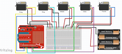
The above image is the wiring diagrm of the Inmoov hand. The five servos are powered by an external supply, the 4 AA batteries. The 4AA batteries should should supply enough power to the servos. The battery power supply is connected to the power rails that is found on the top of the breadboard. The ground of the batteries is connected to the blue rail while the power (positive) of the batteries is connected to the rail next to the red line on the breadboard. The blue rail is the ground rail while the red rail is the power rail.
These rails will be used to connect to each and every servo in this project. Jumper wires or simply wires will be used to be able to make connections from the female connectors of the servos to wherever they must go. The red wire from the servos will go the power rail on the breadboard. The brown or black wire will go to the ground rail on the breadboard. I have labeled the servos according to which finger they are going to control. The most left servo will control the pinky finger. From there, the next servos are for the ring, middle, index, and thumb. After connecting the servos to the the power/ground rails, you will then have one extra wire left on each servo. The wire will usually be yellow or orange, depending on what servos you are using for the project. This is the signal wire. In the wiring diagram above, I denoted the signal wires in different colors to avoid confusion when the signal wires overlap each other.
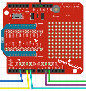
The pinky servo in the diagram has a yellow wire. The ring servo's signal wire is denoted by a light blue (cyan) wire. The middle servo's signal wire is denoted by a green wire. The index servo's signal wire is purple and the thumb servo's signal wire is blue. A close up of where they connect to on the Arduino's XBee shield is shown below.

The pinky servo is connected to Pin 5. The ring servo is connected to Pin 6. The middle servo is connected to Pin 11. The index servo is connected to Pin 10. The thumb servo is connected to Pin 3. In the actual wiring, the SparkFun XBee shield will be stacked on top of the Arduino Uno and the XBee module will also be placed on top of the XBee shield. Also, a side note, you must make sure that the XBee module is not connected to the Arduino when uploading a code. You could remove the XBee module or the shield itself to upload a code onto the Arduino.
Codes Used with the Adafruit Servo Shield
Before I did the project without a shield, I attempted to use a servo shield from Adafruit: https://www.adafruit.com/products/1411
But I didn't really have much luck with using it since I couldn't really understand on how to use its library and to control the servos the way I wanted it to. I tried about 3 different codes that I written to be used with the Adafruit servo shield. I thought I fully understood how to use the shield when I wrote the last code for it. But when it came to testing the codes out, the code didn't work as I planned to.
The code did get the servos to move with each bending of each flex sensor. That worked. The problem that I encountered was that I couldn't obtain the full range of motion of the servos. For example, when I close a finger on the glove, the corresponding finger on the hand would not close. It wouldn't close because the servo didn't do a complete 180 degree motion. The code wouldn't let the servos do the full 180 degree turn. It can't remember how much rotation it did, but I have a video of it on YouTube at https://youtu.be/Y3rPUIiKFwU. After watching the video, I now remember that there would be certain times where the hand would just not respond to the glove.
So, in case anyone wants to use the shield and see what I have come up with in regards to the codes, I have shared them in this post. Maybe you can look over the code and try to understand and find the error(s) that I've done to fix the code. The shield also helps to make the wiring look more cleaner (less messy) since you wouldn't need a breadboard to power the servos. So the following are the codes, starting with the glove code.
// Gerardo Ramos Glove Code V5
// I decided to combine two instructables Arduino code for this glove code.
// One from Gabry295 with his wireless hand and one from dschurman with his robotic hand.
// In this code, I used the Adafruit shield. So, I have to use pwm values and not the
// angles.

int flexpinky   = A0;  // Create names for the analog inputs on the LilyPad
int flexring    = A1;
int flexmiddle  = A2;
int flexindex   = A3;
int flexthumb   = A4;

void setup()
{

Serial.begin(9600);

pinMode(flexpinky,  INPUT);  // Make the ananlog pins as input.
pinMode(flexring,   INPUT);
pinMode(flexmiddle, INPUT);
pinMode(flexindex,  INPUT);
pinMode(flexthumb,  INPUT);
}

void loop()
{
  // Defines analog input variables
  int flex1 = analogRead(flexpinky);  // Read the analog values of the flex sensors.
  int flex2 = analogRead(flexring);
  int flex3 = analogRead(flexmiddle);
  int flex4 = analogRead(flexindex);
  int flex5 = analogRead(flexthumb);

//Serial.println("<");     // You can this section to calibrate your angle outputs by first
//Serial.println(flex1);     // checking what are the minimum and maximum readings of the flex
//Serial.println(flex2);     // sensors when you are closing and opening your hands.
//Serial.println(flex3);     // Once you have calibrated the sensor readings, you can comment
//Serial.println(flex4);     // these lines out.
//Serial.println(flex5);


  // Defines "pos" variables as being proportional to the flex inputs.
  // With the values you got from doing the flex sensor readings above, you can remap the       // values.
  // I decided to do each finger individually, thus the different values for each finger.
    int pos1 = map(flex1,600,830,0,180);
  pos1 = constrain(pos1,0,180);

  int pos2 = map(flex2,730,860,0,180);
  pos2 = constrain(pos2,0,180);

  int pos3 = map(flex3,730,860,0,180);
  pos3 = constrain(pos3,0,180);

  int pos4 = map(flex4,640,840,0,180);
  pos4 = constrain(pos4,0,180);

  int pos5 = map(flex5,752,810,0,180);
  pos5 = constrain(pos5,0,180);

Serial.write("<");     // This is what is being sent from the glove's XBee module.
Serial.write(pos1);
Serial.write(pos2);
Serial.write(pos3);
Serial.write(pos4);
Serial.write(pos5);

//Serial.println("<");    // You can use these lines if you want to make sure that
//Serial.println(pos1);   // the program is sending the right values when you are
//Serial.println(pos2);   // opening and closing your hand.
//Serial.println(pos3);
//Serial.println(pos4);
//Serial.println(pos5);

  delay(30);
}
The glove code used with the Adafruit servo shield looks really identical to the glove code that doesn't use the Adafruit servo shield. The following code is for the hand. This code looks different because of the use of the Adafruit PWM/Servo Shield.
// Gerardo Ramos Robotic Hand Code V5

// This code is made by combining different parts of two existing codes on instructables.com

// One from Gabry295 and the other from dschurman. One was a wireless robotic hand
// while the
// other was a wired robotic hand. I used both programs to make this program. Here, I am
// using the Adafruit servo shield, so the <Servo.h> library won't be used.

#include <Wire.h>
#include <Adafruit_PWMServoDriver.h>

Adafruit_PWMServoDriver pwm = Adafruit_PWMServoDriver();

// Assign the servos to a specific channel on the Adafruit Servo Shield
int servopinky  = 1;
int servoring   = 2;
int servomiddle = 3;
int servoindex  = 4;
int servothumb  = 5;

int angpinky  = 0;
int angring   = 0;
int angmiddle = 0;
int angindex  = 0;
int angthumb  = 0;


byte startPackage;  // Variable that will contain the character of start package

#define SERVOMIN 150  //
#define SERVOMAX 600

void setup()
{
  Serial.begin(9600);
  // Attach the servos to their respective pins
  pwm.begin();
  pwm.setPWMFreq(60);
}

//void setAngle(int channel, int angle)
//{
//  long ticks = ((1000L + (1000L*angle/180L))*4096L)/20000L;
//  pwm.setPWM(channel,0,ticks);
//}

void loop()
{
  if(Serial.available()) {
    startPackage = Serial.read();
    angpinky     = Serial.read();
    angring      = Serial.read();
    angmiddle    = Serial.read();
    angindex     = Serial.read();
    angthumb     = Serial.read();

    angpinky  = map(angpinky,0,180,SERVOMIN,SERVOMAX);
    angring   = map(angring,0,180,SERVOMIN,SERVOMAX);
    angmiddle = map(angmiddle,0,180,SERVOMIN,SERVOMAX);
    angindex  = map(angindex,0,180,SERVOMIN,SERVOMAX);
    angthumb  = map(angthumb,0,180,SERVOMIN,SERVOMAX);

    if(startPackage == '<'){
      //setAngle(servopinky,angpinky);
      //setAngle(servoring,angring);
      //setAngle(servomiddle,angmiddle);
      //setAngle(servoindex,angindex);
      //setAngle(servothumb,angthumb);

      pwm.setPWM(servopinky,0,angpinky);
      pwm.setPWM(servoring,0,angring);
      pwm.setPWM(servomiddle,0,angmiddle);
      pwm.setPWM(servoindex,0,angindex);
      pwm.setPWM(servothumb,0,angthumb);
    }
  }
  delay(30);
}
So those are the codes I used when I was attempting to use the Adafruit Servo shield. It has been a while since I worked on this code so I can't really explain it very well and I still didn't fully understood how to use the shield at the time. I remember I also looked at another code that used the servo shield to control a hexapod. That is where I go the function setAngle. I can't remember the website where I saw this code. Well, I hope this helps with anyone that is trying to do this project. I may also update this post with the wiring of the glove in the future if someone needs it.
