Autonomous Rover Part 6: Troubleshooting
Autonomous Rover Part 6: Troubleshooting
Jan 31, 2018
Gerardo Ramos
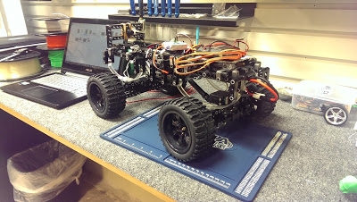
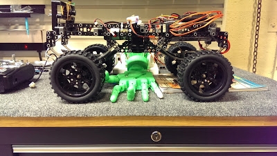
Ordered a power module (PM) from Amazon for the Ardupilot Mega and received it a couple weeks ago. Below is a picture of the PM.
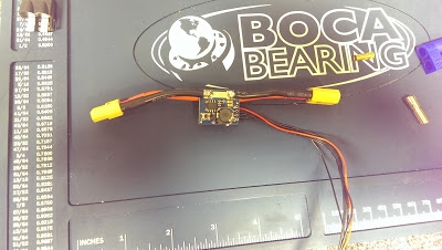
It's not the one from 3DR, the one I was supposed to get from 3DR didn't come with the APM when I received. But I've talked to them and they told they would send me one So the PM that I got from Amazon had connectors that were different from the battery and ESC connecter of the MINDS-i robot. The PM had XT60 connectors while the MINDS-i robot have tamiya connectors.
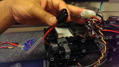
The PM is supposed to go in between the battery and the ESC of the rover. But the connectors on the PM are different from the rover's connections so I had to find a way to be able to connect the PM to the battery and ESC. The purpose of the PM is to be able to provide a safe voltage from the battery to the APM. So I looked around the workshop and found a couple of connectors and bullets that can help me create a connection between the PM and the battery and ESC.
In the shop I found a tamiya connector with wires already hooked into it.
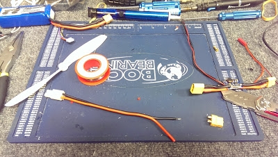
I decided to cut it a little shorter so I won't have an excessive length of wire connections. I soldered an XT60 connector on the other end and used electrical tape to help seal off the solder joints from the connector to the wires. What I got is shown in the following pic.
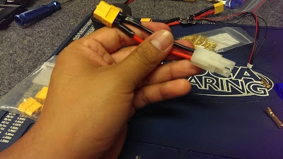
This then can connect the battery of the rover to one end of the PM. The connection so far looks like this:
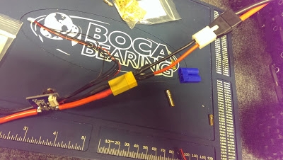
The next thing I had to do was to make the connection between the PM and the ESC. My first attempt of doing this consisted of using an XT60 connector, some short wires and bullets for the other end of the wire. The layout and the final product after soldering and using electrical tape is shown below.
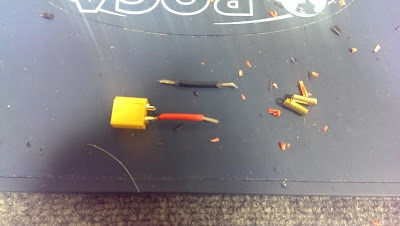
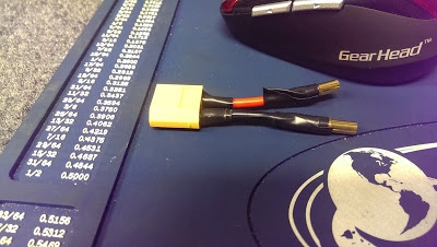
So the this short adapter that I made did not quite work well with connection on the ESC side. The bullets didn't create a firm connection. It was a little loose that the power from the battery would make on and off connections with the ESC. So I had to find another way to connect the PM to the ESC.
My initial goal was to not cut any wires or remove the connectors on either the battery or ESC. But I ended up having to remove the connector off from the ESC. I just did a little bit of playing around with the tamiya connector until I eventually got it off. Once I did that, I just used a XT60 connector and soldered it onto the ends of the wires from the ESC. Then I just taped it off with some electrical tape.
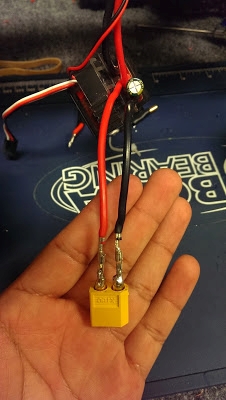
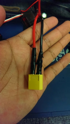
Now I had the proper connections to make so I tested out the PM. But, the PM didn't work. So I looked online and found that where I got the PM from, a previous customer had an issue with this specific PM. His issue had to do with a solder bridge between two solder joints that shouldn't touch each. I fixed the solder bridge but it didn't help. Another thing that I realized was that there was a component on the PM that seems to have broken off.
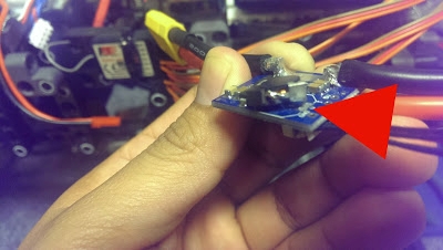
I tried testing if that was the problem by making the two separate touch each other while the connection is made between the PM and the rover's battery. But it didn't do nothing. I believe this may be the problem because online this part seemed to be intact with the small board of the PM. There also seems to be a small black piece broken off. But in the meantime I'll be waiting for the PM from 3DR to arrive. I have no doubts on the 3DR's PM.
I just went back to test out the different features of Mission Planner and the APM. Then out of nowhere I came across a new problem: the rover won't steer at all. It won't steer in manual mode or in auto mode. I have a video of it below. I also sent this video to 3DRobotics so they can see what kind of problem I was having with the board. They were very help in giving suggestions on what the problem might be and were really quick to reply to emails.
I tested the servo to make sure that it wasn't that servo that went bad. I just simply plugged it into the 3D printed robotic hand and tested it with the glove. The servo checked out good, it responded and moved to the movements of the glove. So I knew then that the servo wasn't the problem here. I then thought I had the wiring wrong so I rewired the whole from scratch a couple times to make sure it wasn't because of wrong connections. But that wasn't the problem either. I then went ahead and experimented with some of the parameters in Mission Planner to try to change what channel on the transmitter controls the servo.
But that didn't help either. I then decided to power the servo separately with a different power source and only have its signal wire connected to the APM's output. But, again, it didn't solve the issue. I checked the voltage across the output 1, where the servo is connected, and did get a good amount of voltage: 5.17 volts. So it really got me confused as to what the problem was. I also decided to switch the outputs between the ESC and the servo. I moved the servo to output 3 and the ESC to ouput 1. But that didn't help either. The rover servo still wouldn't steer but the throttle still worked, just this time with channel 1 instead.
So what I decided to do one day was to check if I can still steer the rover if I just controlled via the receiver only and without the APM. When I tried this, I found out that I couldn't even control the rover at all. No steering or throttle. I then thought that maybe I just need to bind the receiver and transmitter. I thought maybe the APM did something to the binding between the transmitter and receiver. But when I tried to bind them, nothing happened. I followed the instructions on how to bind the FlySky FS-T6 transmitter with its receiver but it didn't work. The receiver was supposed to light up. That's when I realized that the receiver doesn't even turn on with the ESC connected to it. That's when I figured that maybe it had something to do with the ESC of the car.
I then looked around the workshop to find another ESC to borrow to see if that's what the problem was. I decided to use Jeep's ESC from Dominic's project. The testing of the ESC can be seen in the video below.
I've concluded that it must be the ESC of the rover that was causing the rover to not steer at all. I have already ordered a new ESC from MINDS-i for the rover:
http://mindsirobotics.com/80amp-electronic-speed-controller.html
I called up MINDS-i robotics and told them about the situation. I was told that this new ESC is much more reliable than the one that came with the kit. He said that their goal was to include this new ESC in future kits instead of the one that is included now. So right now I'm just waiting for the new ESC to come and for the PM to come from 3DR.
I also forgot to mention that I swapped out the wheels on the rover. I found some wheels that were lying around and asked Bryan if he was going to use them. He said I could use them so I just slapped them on to give the rover a slightly different look. Here's a picture of the wheels before.
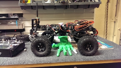
And a picture of the rover on new wheels.
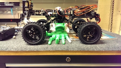
It may be a little a hard to see the difference but the new wheels are larger in diameter and more glossier in person than the original wheels. The new wheels also sport lower profile tires. So I'm not sure how this will translate to off road driving but I will see once I can get the rover up and running.
