Racing Power Wheels Part 9: Demonstration, Test Run, and Steering Problems
Racing Power Wheels Part 9: Demonstration, Test Run, and Steering Problems
Apr 16, 2018
Gerardo Ramos
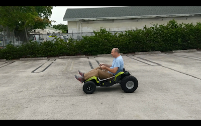
You can see some of the testing that we did in the videos above. In the first video above, we were simply testing the motor with the chain, sprockets, and axle. In the second video, Mihai from Boca Bearings was testing the Power Wheels Boca Dune Racer around the building.
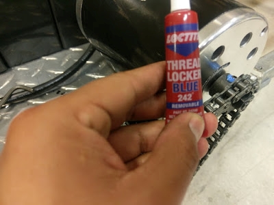
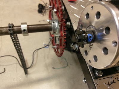
In the first video, you can see that the Power Wheels seem to pick up lots of speed by looking at how fast the wheels were spinning. I can't really remember if we went full throttle but I think we did. After doing some more testing of the motor with the chain and axle, the set screws on the motor sprocket would fling out. So I went to Lowe's to get some Loctite Blue Thread Locker to keep the screws from coming out. Below are some pictures of the Loctite and on the set screws.
Before actually test running the Power Wheels, the hand throttle malfunctioned. It wouldn't let the motor come to rest. It was stuck at some minimum throttle input that kept the motor running constantly when the hand throttle was let go. So to see if it was the throttle that was causing this problem, me and our new engineering intern, Luke, tested the controller with a potentiometer. We figured that the hand throttle's signal pin only had a varying voltage from 0 to 4 point something volts. So we found a potentiometer laying around and connected it to the motor controller. To my amazement, the potentiometer worked in controlling the motor from rest to its top speed. So we pinpointed the throttle as the failing part.
So I ordered two new throttles, just in case another goes bad. I ordered two different throttles. One a thumb throttle from TNC Scooters, http://tncscooters.com/index.php?route=product/product&path=65_79_83&product_id=76.
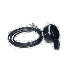
The second throttle is a half grip throttle. I got it from Monster Scooter Parts since they were out of stock at TNC Scooters. The link to the half grip throttle from Monster Scooters is http://www.monsterscooterparts.com/thswasformia.html. Below are some pictures of this throttle and it is the one in use now.
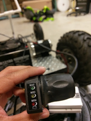
This half throttle also has a fourth wire that I will not be using. The fourth wire is to check the voltage of the battery but I don't think the controller that we are using has the proper pin location for this pin to be connected to.
The second video was taken on the first day that we went to test run the Power Wheels around the building. Many of us went for a ride on it. About 6 of us tested the Power Wheels Dune Racer. I only recorded the short clip of Mihai testing the Power Wheels.
During this testing day, new problems were encountered. The first and already mentioned before problem was the brakes. The brakes weren't that good in stopping the Power Wheels from full speed. Eventually, the key that held the brake disc in place to the axle fell out during testing due to not installing lock collars. This prevented us from going full speed on the Power Wheels. I attempted to go full throttle but I would eventually let go of the throttle because of not being able to stop instantly. We already have the new hydraulic brake kit, it's just a matter of time of installing it on the Power Wheels.
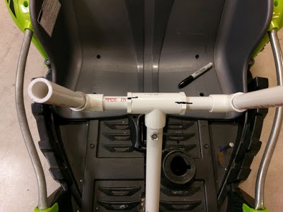
The newest problem encountered during the test drive was the steering. The steering was pretty twitchy/sensitive at higher speeds and made it very unstable to drive at higher speeds. This also stopped me from going full throttle. After testing, I decided to fix the alignment of the front wheels since they weren't properly aligned. They were aligned in the beginning but at the time I didn't install the jam nuts to prevent the alignment from going out. But before doing that, I decided to first work on the steering shaft. There was some play in the steering shaft so I thought that maybe the play in the steering shaft contributed to the instability at higher speeds. To make the steering shaft have less play, I used a longer piece of PVC pipe to reach the bottom of the metal steering shaft for it to have less play. Below is a picture of the steering shaft with the first used PVC piping over it.
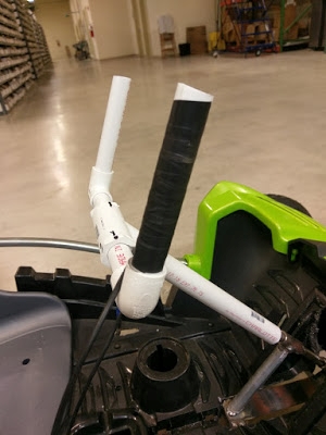
The new longer PVC pipe reaches the support column and over a thicker part of the steering shaft. This helped the PVC pipe in having less play. The new PVC pipe installed can be seen below.
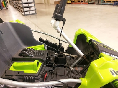
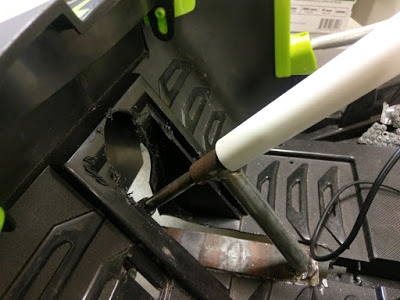
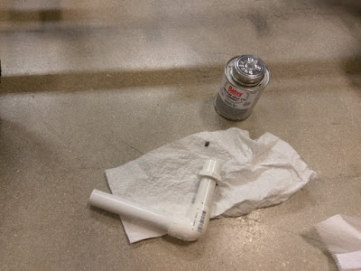
Bryan also added some tape around the middle of the steering shaft to make the PVC fit more snug over it which helped. I also had to reapply some more cement glue to the steering components since they come loose during the testing. Below are some pictures of the steering PVC parts being glue together.
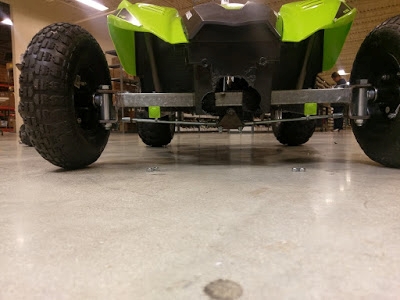
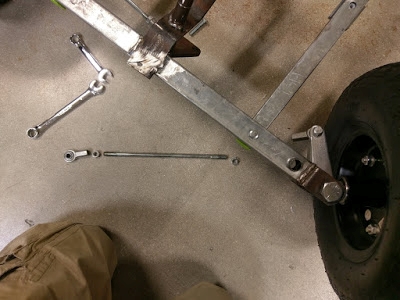
Once I had the steering shaft more rigid than before, I went ahead and worked on the alignment of the front tires. In the picture below, you can see that I have no jam nuts on the tie rods. The jam nuts are on the floor in the picture below. You could also see that the front tires seemed to have a toe out setup before fixing it.
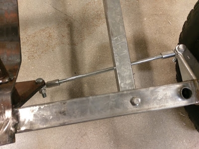
Here's a closer look of the tie rod with no jam nuts.
I removed the tie rod and installed the jam nuts on the tie rod. You can see the tie rod removed below and with the nuts threaded onto the tie rod.
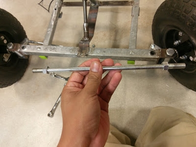
With the tie rods installed with the jam nuts, I eyeballed the alignment of the front tires with the intention of having zero toe. Then I tightened the jam nuts against the tie rod ends. The final results are below.
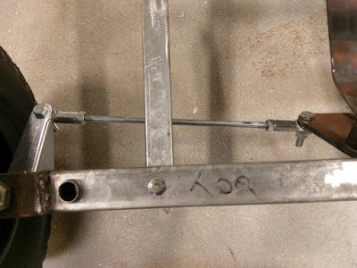
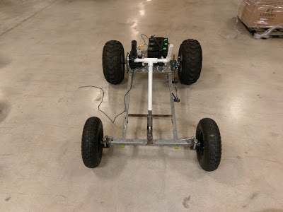
The alignment may not be perfect but it is much better than before. Since at this time I had the Power Wheels body off of the frame, I went ahead and worked on the mounting of the motor because the motor moved during some parts of the chain.
I originally only used 3 bolts to mount down the motor. There was a fourth hole on the mount but I didn't drill the fourth hole in the frame because it was really close to a edge of the cross member in the rear side of the frame. Below is an image of the diamond plating where the motor mounts to. Ignore the numbers written on the plating. They were used as references when I first drilled the mounting holes into them.
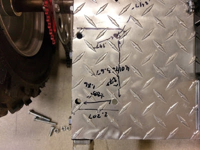
In the picture above, you can see that I am just barely staring to drill the fourth hole towards the top on the right. I drilled slowly and checked periodically underneath the frame to see if it won't drill into the edge of the cross bar underneath the plating. Everything seemed ok so I drilled it all the way through. Below is a picture of the motor mounted with the newly drilled hole.
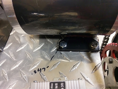
From the bottom, you can see that the new hole was somewhat close to the edge. The bolt I am referring to is the shorter bolt. That is where I drilled the new hole.
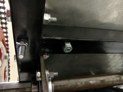
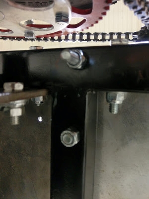
With the motor mounted with all four bolts, the motor moved less but still moved. So I think the chain may be too tight. I might try to make the bolt holes more elongated to be able to adjust the tension of the chain. The final setup so far of the motor, batteries, and controller can be seen below.
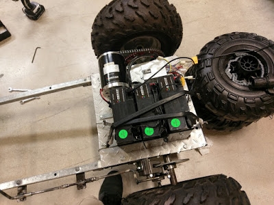
So some days later I went ahead and retested the Power Wheels to see how it's running. The steering was a little bit better not significantly. You could still feel the sensitivity of the steering at high speeds. So it wasn't entirely fixed. Also during this testing, the front left wheel just broke off. The rim sheared off the rim's hub. Below are some shots of the failed wheel.
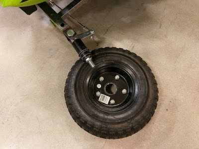
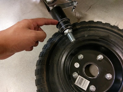
You can see where I am pointing the small surface area that the wheels were attached to. It's very thin and the wheel is basically just two thin plates bolted together and welded at the hub. This happened on a right turn. So all the weight of the Power Wheels and the driver was being directed to front left wheel during the turn. I guess the wheel couldn't handle the loading and just sheared off. I will be going to Harbor Freight again soon to look around for some beefier wheels. I am thinking of getting wheels that are 1 piece, unlike these two pieces that are bolted together.
So after this I was doing some research on how to fix the steering and I came across some interesting information. I found out that the reason why my steering is so sensitive is because of having negative caster. Negative caster causes instability issues while positive caster creates stable steering at high speed. I found a couple videos that helped to explain caster and how it affects steering. The first video below explains what caster is.
In this second video I found, I learned more about caster and the other aspects of wheel alignments. But some of those aspects are not really necessary in this setup. The video is about race cars and their wheel alignment. But there was some very helpful information.
So it suggested to have some positive camber, where the steering axis is slightly tilted towards the back of the car at the top of the steering axis. So I took a few pictures of the steering axis of the Power Wheels Dune Racer and I see that our steering has negative caster, which isn't desired. You can in the picture below that we have some negative caster.
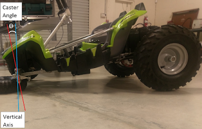
The blue line is the vertical axis that I drew to the best of my ability and the red line is the steering axis. If the wheel was placed on the axle, its tire contact patch would be directly below the axle and this would mean the tire contact patch would be in front of the steering axis. This is not a good. When going at high speeds and turning, the contact patch would be either to the left or the right of the steering axis and in front of it. At this moment, the contact patch would naturally want to go behind the steering axis but it can't because it is restricted by the tie rods and the spindles. This explains why at high speeds, when making a slight turn on the steering wheel, the car feels like it wants to do a sharp turn. The contact patch wants to go behind the steering axis. Experiencing this in person is quite scary to me in my opinion. This could maybe make the Power Wheels flip over at high speeds.
A good similar example of this would be caster wheels that are found on shopping carts and office chairs. When the contact path of the caster wheel is in front of the steering axis/pivot and pushed, it would want to go behind the steering axis. So I will have to fix the caster angle of the Power Wheels.
Fixing the caster shouldn't be too difficult. I am planning on getting another set or 2 of the spindle brackets from BMI Karts and I will need to find some square tubing laying around. I believe I may still have some bed frame tubing. I can cut the tubing to the same length as the first one and then get the brackets welded onto the ends but a positive caster angle.
The first brackets were welded to be parallel with the front bar as you can see below. They weren't welded to provide any type of caster.
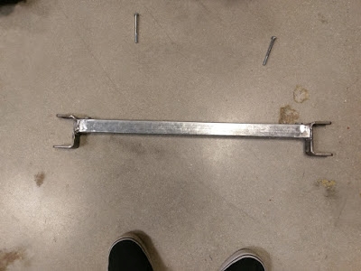
The caster was created by the smaller wheels at the front of the Power Wheels. This caused the steering axis to tilt forward and create negative caster. With larger wheels or wheels the same size as the rear wheels, the caster would be at 0 degrees. But I will still need to weld the brackets slightly leaning back to create positive caster. I will just need to figure out and experiment how much positive caster I need. Too much positive caster can make the Power Wheels hard to steer at higher speeds.
So for the next blog post I will hopefully have the new hydraulic brake kit installed and a new front bar with the brackets welded to create positive caster. I hope this will have to stabilize the steering at higher speeds. Thanks for reading.
