Instructables-Pinball Machine
Instructables-Pinball Machine
Apr 12, 2021
James Laumeyer
James Laumeyer
Pinball machine instructible
Grabcad files:
https://grabcad.com/james.laumeyer-1/models
Components:
2 - sheets of 1/2in plywood
2- 2x4 pieces of lumber
1 - 1in dowel rod
1 - box of finishing screws or finish nailer
https://www.homedepot.com/p/GRK-Fasteners-8-x-1-1-4-in-Star-Drive-Trim-Head-Finish-Screw-100-Pack-96055/204837649
10 - bearings (R16-ZZC PS2) 1*2*.5in
https://www.bocabearings.com/products/r16-zzc-ps2-3195
5 - 1in Plastic balls
https://www.bocabearings.com/products/1-in-plastic-ball-(1-pc)-19523
(optional) - 1in SI3N4 ceramic balls
Use these in place of plastic balls for a heavier ball for slower game play
https://www.bocabearings.com/products/1-in-c-si3n4-ball-grade-10-(1-pc)-i0000011
3 - pop bumper towers
https://www.pinballlife.com/desega-pop-bumper-assembly.html
2 - flippers (one left and one right)
https://www.pinballlife.com/mm5/merchant.mvc?Screen=PROD&Product_Code=ASE-1587-10X
1 - ball trough
https://www.pinballlife.com/ball-trough-assembly-4-ball.html
2 - sling shot assemblies
https://www.pinballlife.com/data-eastsegastern-slingshot-assembly.html
4 - banks of 24v relays
1 - 24v power supply
1 - power socket
Lots of wire
Spade connectors
2 - 1in pull solenoids.
https://www.mcmaster.com/70155K511-70155K451/
1 - 24v motor
5- Arcade buttons, your choice of size and color
https://www.adafruit.com/category/757
1 – LED strip lights (optional)
4 port wire connectors
https://www.homedepot.com/p/Ideal-34-Yellow-In-Sure-4-Port-Connector-100-Pack-30-1034P/202894312?MERCH=REC-_-searchViewed-_-NA-_-202894312-_-N
1 qt. of Black Stain
1qt. Of lacquer
Tools:
Miter saw.
Oscillating Multitool
Drill
Sandpaper
Painting supplies
Soldering station
3d printer (We used Prusa Mk3)
Hole saw set.
Drill bits
Finish nailer (optional)
Carpenter Square
Sawhorse
Congratulations, you have decided to make a Pinball machine based off the Boca Bearing Design! Now before you get into this project an important thing to note is that our machine has a material cost of about $7-800, pinball electronics are expensive. However, this cost can be cut down to $300-500 if you were to modify our design, use un-sanded plywood, and have the only electronics be the ball return, flippers, and launch system, while using 3d printed parts to make obstacles on the play field.

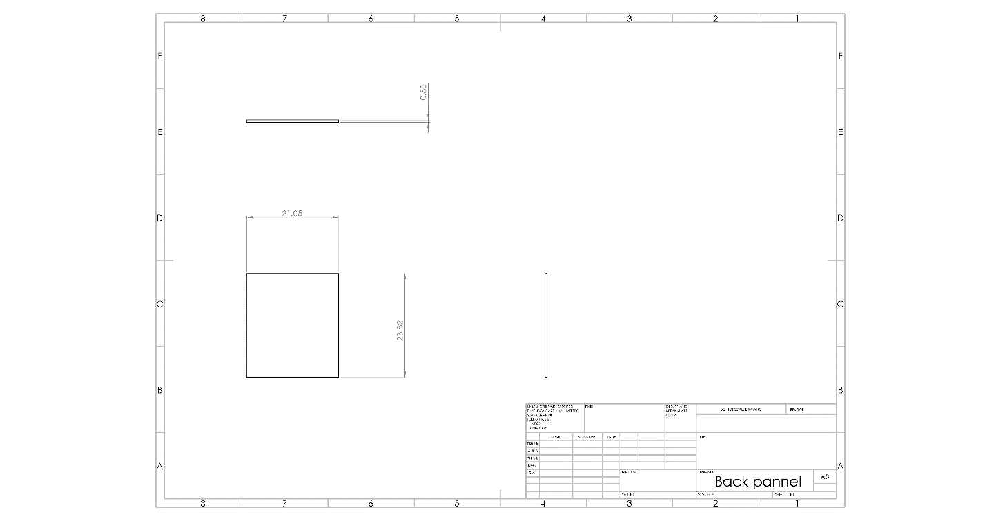
The first step in making the pinball machine is to make the box to house all the electronics and the playfield. To do this the first step is to setup your sawhorses, 2 sheets of plywood, and draw out your cuts as shown in the schematics bellow. One modification you may want to make to the design is to add an inch on each side to the bottom panel so that the sides are sitting on top of it instead of having the bottom nested between the sides


Note: You need two side panels, and the left and right side are identical.
You may have noticed there is no piece specked out for the top flat 10.25in surface on the sides of the box, you will have to take a moment to get some measurements and asses the dimensions for that piece. With that said you do not want to add that part till latter to give a better working clearance. Once you have all these parts cut out, it is time to assemble. For assembling the box, you have two options, the first if you have a finish nailer, I highly recommend using that with a little wood glue to assemble the box it will make your process much quicker. If you do not have a finish nailer you can use a drill and finish screws to assemble the pieces, make sure you drill a pilot hole for every screw on you will have issues with the plywood delaminating.
Now that you have the box taken care of it is time to design your play field. This is where you can take your creativity to the max. Shown below is one example of how to lay out the playfield with the five medium holes being for the spinning pillars and the 3 large ones being for the three-pop bumper. Now you do not need to hold true to this design, even I changed it significantly as I built it. The main things you need to be certain of are that your tolerances are high enough that a ball won’t just get stuck in play, so no gaps less than 1in. You may also notice a bunch of slots in the playfield, these are not necessary unless you want to add rollover switches for a score board which is no simple feat. While an attempt was made to implement a score board with this project there was a large problem where the wires used for signaling where not insulated, and with such a large quantity of them crossing there was a high level of electrical noise which led to false signals. This could potentially be fixed with the use of insolated wires, but this has not been tested. Another thing to note is the large slot in the bottom of the play field that was designed for a 3d printed ball return system. This return system was a failure and the decision was made to go with an off the shelf solution, this slot will not inhibit the implementation of the off the shelf return system though it is not strictly necessary for a functional system.
Once you have the field done it is time to add your mechanism to your play field stays steady in the box. For this you will need a 2x4 and a 21x1in dowel rod. Your first step is to cut two 4in long pieces and drill a 1in hole through them about 1.5in up. This hole is going to be so you can fit a dowel rod through that is going to be your pivot arm. It may be a tight fit but sand the hole until you can fit the dowel through. Once those are affixed your next step is going to be to attacking it to the playfield you want to make sure this piece is centered and looks something like the picture bellow.
Once this is affixed you now need to take some more of that two my four and make the brackets for the inside of the box. You will need to stack two of the below brackets on each side of the box, this will allow the dowel to sit in them and pivot so you can raise the board to work beneath it. You will also need to put some boards on the front inner sides of the box in a place that will not interfere with any of the other components but will leave the playfield at an angle of approximately 6.5degrees.
The inside of your box should look something like the above picture.
Once you are this far now is the time to paint your box if you so choose, we decided to go with a black stain and a gloss varnish on the box but left the play field natural wood. We also added some 1in angled aluminum trim and bellow is how it turned out.
At this time you may want to add some handles to the box to make it easier to move, we went with some 4in black ones but you can use whatever strikes your fancy.
Now you are ready to start the electrical your first step is to install the fused switch plug in the back and the 24v power supply. The diagram bellow shows how you wire up the plug and you want to wire the input voltage for the power supply to the output voltage of the socket. If you are going to add LED lights that have a controller that runs off of 120v AC then I highly suggest that you add a 4 port connector into these lines as well that way you can easily break wires out and solder them to the controller inside the box.
Next you will want to find some place on the inside of your box for your relay panel, you will need one relay for each electronic component that needs to be actuated. For our system we used 13 relays but yours may be higher or lower depending on how you lay it out. There are plenty of tutorials online that explain how to wire relays up much better than I can write here so if you do not know how to deal with relays you should refer to them.
Once you are this far it is now time to add all your components to your play board. If you are following along one component of the play board that was designed successfully in house at Boca Bearings was the spinning pillars, this adds an element off movement and allows for a unique in game obstacle. A picture of it is show bellow.
The final version was designed in such a way that if can be entirely printed on a Prusa MK3 except for the motor and the ten R16-ZZC PS2 bearings that you can find at our website: https://www.bocabearings.com/products/r16-zzc-ps2-3195 . The files for this and can be found on my grabcad account linked here: https://grabcad.com/library/boca-bearing-pinball-machine-1. One thing to note though is that the tolerances are a little fussy with this assembly so you will need to play around a little with your settings to find what works best for your printer.
Another part that you may want to 3d Print is the ball launching mechanism shown below. Now, full disclosure this system is not perfect and is more underpowered than initially expected, but it functions properly with both plastic and Si3N4 bearings. The draw back to this is twofold, plastic balls are cheap, but they create a wicked fast game and will not always trigger something that they hit. The Si3N4 are light enough that they will make it up the play ramp, yet heavy enough that they will cause a more normal play speed and actuation, however they are quite expensive at around $80 a ball. But given that for the purposes of this build and the average home user plastic balls make for a plenty fun game, and the files for this are also up on the grabcad linked above.
There are three other parts in the grabcad file you may find useful as well, those being the flippers, cover for the slingshots and the top half of the ball return system. The reason you may want the to use the top half of the ball return system is as a guide for your ball to be loaded into the launcher, there are other ways to do this, but this is the one we used.
Once you have all your obstacles and other parts attached it is now time to add your guide rails for your launch and return system as well as the buffer around the edge of your playfield to keep your balls from rolling where they should not. For this we used scrap pieces of 3/4in plywood stacked to a thickness of 1.5in. This will take a little bit of fine tuning to your individual field, do not be afraid to add or modify pieces so that the ball runs smoothly through the playfield. Ours ended up looking like the picture below.
Once you have all your pieces installed its time to wire everything up, remember to make sure you have the machine unplugged from the wall as messing with these components with the system powered on could potentially result in serious injury. One thing that we found useful was to make use of a short lead with a spade connector attached to your component followed up with a longer bridging wire in between, this way if you mess up a connection it is supper easy to swap with the proper lead. If you have any buttons that use 5v or 12v LEDs make sure you step down the voltage using a Buck Converter, otherwise you will end up blowing out your lights. Another tip is to use 4 port connectors to split out your power and ground coming out of your power supply, this will make your wiring a lot easier.
Congratulations! Now that your wiring is sorted out your pinball machine is ready to test. A final thing to note is that if you want to make to free standing you can use threaded iron pipe like we did for the legs or leave it flat bottomed and set it up on your workbench. However you chose to set up your machine remember you have accomplished something big and it is now time for you enjoy the fruits of your labor and have fun with it!