LED Programming
LED Programming
Apr 28, 2021
Carmen Riggs
When I joined the skeeball project, I was tasked with the complete development and design of the electronic components. I started with the understanding that there were 3 LED displays which needed to be controlled by a main power switch.
The LEDs were purchased from Amazon, which lacked the required data sheet necessary to understand their input voltage necessary for optimal function. Due to this, I had to do extensive testing on the LEDs with a power supply and multimeter, testing what level of voltage would turn on the LEDs and allow them to be controllable with a battery pack. I found that the necessary level was over 8V, which was contradictory to the Amazon data sheet, which claimed 3V. Additionally, a significant component of testing was to determine if the LEDs were common anode or common cathode LEDs. This difference controls the flow, and additionally determines if the LED is controlled via ground or power.
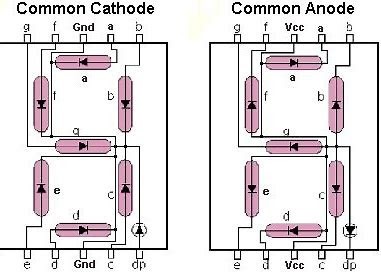
Figure 1: Common Cathode vs Common Anode
I determined that the LEDs were common anode via testing the pins as either ground or power. This then impacted the order which the pins would register as the individual lines, making up the visible numbers. As seen in Figure 2, the segments are referenced by letters A-G, representing segments 1-7. This information played a key factor in designing the wiring and resistor layout.

Figure 2: LED Segment Ordering with Number/Letter Values
Due to the high voltage requirement of 8V, I needed to design a resistor layout with 220Ω resistors on the perforated breadboards to protect the Arduino Mega, which had a maximum voltage tolerance of 5V. With these resistors, they acted as a step down for the voltage and would allow the LED to still get the 8V+ necessary but cut the voltage down to 5V to remain functional with the Arduino. If these resistors were not laid properly or included, then the Arduino would’ve short circuited. With the design of the resistors, it was important to link them by soldering onto the board, however it was a delicate process because if any of the singular resistor solder touched another resistor, it could not be controlled individually. This was an extensive process, lasting over 6 hours as there were 2 boards which needed to be designed, soldered, and placed onto each of the LED’s.

Figure 3: Resistor layout on perforated breadboard
After designing and implementing the resistor layout on the perforated breadboard, I tested the design to ensure that the LEDs were properly working, and all the segments were lighting up with input voltage.

Figure 4: Testing the Resistor Design with Arduino and Multimeter
As seen in figure 4, the multimeter was attached to the 7 Segment LED, with the black alligator clip leading to ground, and the red to power. The LED had previously been programmed with the Arduino to light up individual segments of the LED, of which will be described and mentioned later in the post. When the LEDs were sufficiently debugged and adjusted, the rest of the perforated boards were soldered, a process which took many attempts given the proximity of the resistors beside each other.
After all 6 of the perforated boards were soldered and finished, the LEDs were attached, and its wires soldered directly onto the perforated boards. Additionally, wires were connected to all resistors solder, to create a connection between the LED segment pins and the Arduino.
Figure 5: Wired and soldered LEDs with perforated boards attached to back pins
The finished LED wiring is seen in figure 5, showing the 7 wires coming from each individual LED and all 6 perforated boards attached to the back of the LED via soldered pins. The boards, wires, and resistors were covered with electrical tape for protection of the electronics and additionally for handing with flowing current. Additionally, the LEDss were wired to connect to a battery pack which would provide and regulate the amount of current going into the LEDs.
Following the LEDs being finished electronically, the second requirement of the project was begun, that being for the LED to process and register input signals from switches. These switches were used to increment the LED values when it sensed a ball weight on it. To create connections from the switches to the LED, as seen in figure 6, wires were soldered onto the switches and the switches were attached to a power switch mounted on the side of the skeeball.

Figure 6: Mounted switches on bottom of skeeball, with wires leading to Arduino and LED
These wires were stripped on the end, and the individual copper lines were soldered in order to create a strong enough tip to insert into the Arduino. There were three lengths of wires, corresponding to the three varied heights of the skeeball ball boxes. Initially in the project, all 3 wires were connected to the switch, however due to a lack of data sheet, eventually the switches were reduced to two wires as explained later in the post. Additionally, a large hole was drilled into the top of the skeeball machine, seen in figure 11, in order to allow the wires to flow unrestricted into the main electronics housing at the top of the machine. This also allowed the wires to be completely internally kept inside the machine, for both protection of the electronics, as well as functionality of the closing skeeball machine back door.

Figure 7: Angled view of the switches mounted with wires

Figure 8: Front view of skeeball with wires leading from switches
After the switches were mounted, soldered, and wired, the power system needed to be configured, wired, soldered, and debugged. A simple off and on switch was connected to three wires, one leading to the Arduino to register input of power, one leading to ground, and another leading to power from the battery pack. This power switch was mounted via a drilled hole in the side of the skeeball machine, with its cords leading into the inside of the machine. Cable management was implemented by grouping together the LED wires, the switch wires, and the power wires with zip ties, and the groups accordingly separated by Arduino input wires, power, and ground.

Figure 9: Inside components of the power switch

Figure 10: Outside view of power switch
This power switch, as previously mentioned, was attached to a battery pack to supply regulated power. This battery pack contains 6 AA batteries, which can be changed as needed for long term use. The pack was wired into a perforated breadboard and connected to the switches, with the main plug seen in figure 11 connecting to the Arduino for power. This was preferable over connecting a large wall cable because of the portability of the battery pack for testing away from the Boca Bearings intern lab. However, this setup does allow for future modifications if such a wall cable is ever desired.

Figure 11: Battery pack wired
After the switches were wired to the battery pack, all the cables and cords were connected to the Arduino to test the response to power input. This process included software configuration as well, with each wire connecting into the Arduino needing to be variably established in order to elicit a response to specific segments. As seen in figure 12, the LEDs were labeled A-C, to maintain understanding of their pins and to stay organized.

Figure 12: Finished wiring for LEDs, Arduino, battery pack, and switches
The LEDs were tested and deemed responsive to the power input, seen in figure 13. Due to their amount of wiring and shape, a housing, seen in figure 13, was created for them by the mechanical interns. This housing allowed for the LEDs to stand vertical and the wiring to be protected from unnecessary bending. This housing will be painted in the future to match the color scheme of the rest of the machine. A conjoined electronics housing box will also be constructed to provide long term protection of the electronics.

Figure 13: Testing for power with LEDs in mounted LED housing
Following the initial success with the power response, there was significant struggling with getting the switches to respond to input. This was determined to be due to the switches having only one ground/power pin and one input pin, with the third pin being obsolete. The switches were rewired, seen in figure 14, to accommodate this new discovery, and additionally, their wires were soldered and connected to female-to-female wires in order for ease of connection with the Arduino.
Figure 13: Rewired switches for debugged ground/power and input pins
Each of the rewired wires connected to female pins were covered in electrical tape for protection and organized by either power or input wires with zip cables.

Figure 14: Rewired and organized wires covered with electrical tape
With all the wires now covered, the pins were ready to be inserted into the Arduino and the software debugging begun.

Figure 15: Pins inserted into the Arduino
The software development for the project was quite linear, beginning with using a sample 7 segment LED software code to evaluate whether the LEDs were usable when they were unresponsive to the 3V power as stated by the invalid Amazon data sheet. After that, the code used for the project was developed and debugged according to the needs of the system.

Figure 16: Definitions of LED segment pins in Arduino mega
The code begun by definition statements, which established the individual pin values that each LED segment wire was connected to on the Arduino. This initial definition section was not functional due to the wires not being connected to the right segment pins. This problem was solved by debugging and lighting up individual segments with their corresponding pin value. The process was repeated for all 7 segments on each LED.
[A picture containing text, screenshot, receipt Description automatically generated]

Figure 17: Switch defining statements and variable value setting
The switches needed the be also defined as variables, and the values following the SWITCH1, SWITCH2, and SWITCH3 variable names are their pin values. These switches would only be registered by specific pins on the Arduino mega board, and their values were determined via the website’s documentation provided for the Mega. Additionally, the int statements establish the variables as single digit numbers and set the value equal to zero to allow for linear counting. The const int declaration establishes the values for each of the switches, which register as the counting increments for the LED when the switches are pressed.

Figure 18: Declaring the LED as output for segment display
The pinMode statements seen in figure 18 reference the act of setting the LEDs on a display state, as opposed to declaring them for taking in information.
[A picture containing text Description automatically generated]

Figure 19: Switch statements for registering input
As seen in figure 19, there is a second instant of the pinMode declarations, except involving the switches. This INPUT_PULLUP allows for the switches to be set to registering input, as determined by pressure pushing the switch wire down via either hands or balls. Additionally, the attachInterrupt allows the software to interrupt the code loop to allow the switch input to be processed by the Arduino without slowing the processing loop speed. This is repeated for all switches as seen.
[Graphical user interface, application Description automatically generated]
Figure 20: If statement for switch 1
This if statement declares that if there is an input from the switch, the value increments by the amount of time the input is received. This new value is then stored in the previous switch1 variable, creating a loop of ever-increasing values unless stopped by a exit condition. This process was repeated for all switches in the same manner.
[Diagram Description automatically generated with low confidence]

Figure 21: Exit loop statement
This loop is the exit statement as mentioned previously, declaring that if the value goes over 1000, the counter will begin at 0 again. This is additionally paired with a num = 980 statement, which due to the switch values is the maximum number the counting can go to without starting at zero.
[Graphical user interface, text, application Description automatically generated]

Figure 22: Value establishing for LEDs
This grouping of if/else statement declares that if the value of the count is under a certain range, to only activate specific LEDs. This is seen in the comments in the first if (num<10), which references the statement that if the value of the count is under 10, to only activate numbers on the first LED. This is then also established for the second and third blocks of statements, which correspondingly implement the same concept however, in application to under 100 and over 100. If the value is under 100, only the first two LEDs are activated, representing numbers such as 20, 60, and 80. If the value is over 100, all three LEDs are activated, displaying numbers such as 120, 160, and 180.
[Text, table Description automatically generated]

Figure 23: Displaying specific numbers on the LEDs
This code references the specific LED segment display code, which is unique to each number. As seen in figure 23, this example references the number 0, and displays a perfect circle. The LOW and HIGH values attached to each segment value correspond to which values are activated and which are deactivated, respectively. This process was repeated for all numbers 0-9 across all 3 LEDs.
[Graphical user interface, application Description automatically generated]
Figure 24: Delay statement
This final delay statement allows for the code to have time in between loops, and to establish a default state if the switch buttons are not pressed.