Flow Hydro-Electric Energy Converter Completion
Flow Hydro-Electric Energy Converter Completion
Aug 27, 2021
Boca Bearings
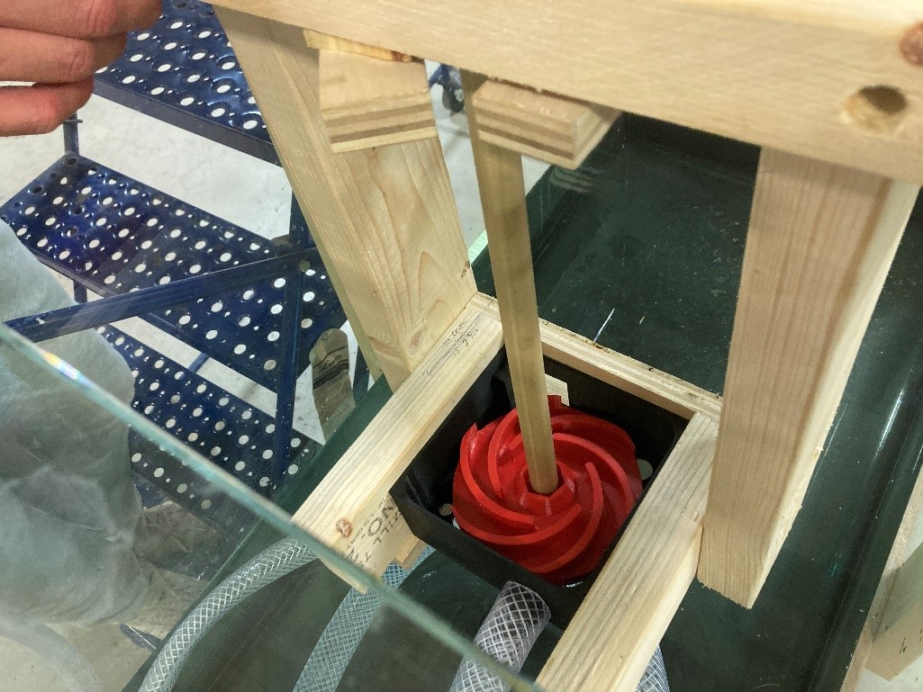
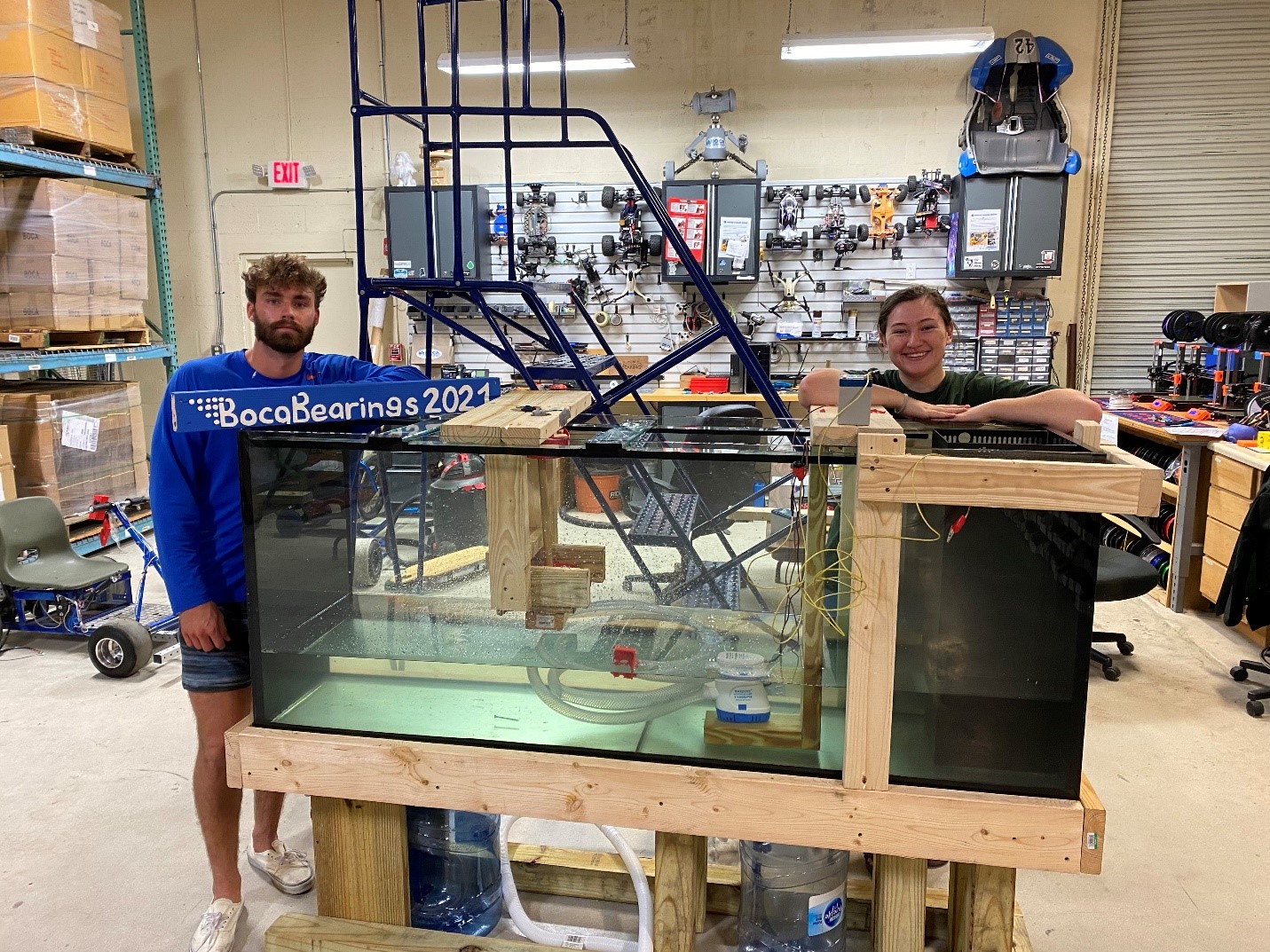
The initial set up of the project included a box leveled on top of the tank, in which a second bilge pump and tube entered and exited the box.
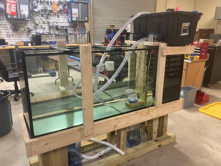
This was initially decided to increase the forces acting upon the turbine through the addition of gravity forces. However, the limitation with this that lead to the dismissal of this idea was the sealing of the tube going into the box.

Tyler used a silicone glue in order to secure the tube, however due to time constraints it was unable to seal properly and therefore it leaked.
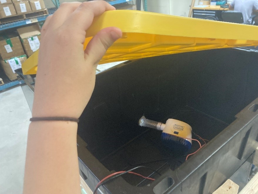
In remedy of this issue, Carmen and Tyler decided to have one bilge pump situated at the bottom of the tank, and the tube leading directly over the turbine. In this, the design idea was to have the water fall back into the tank and then be recirculated by the bilge pump, creating a loop.
The Turbine was designed by Tyler and printed on the Boca Bearings 3D printer. There were 2 turbines printed in order to have a back up should the first break or malfunction.

A long wooden dowel bought from Lowes was then epoxied into the center hole of the turbine. This was given a substantial curing time, however when the turbine was checked on the assembly day, the epoxy was still sticky.
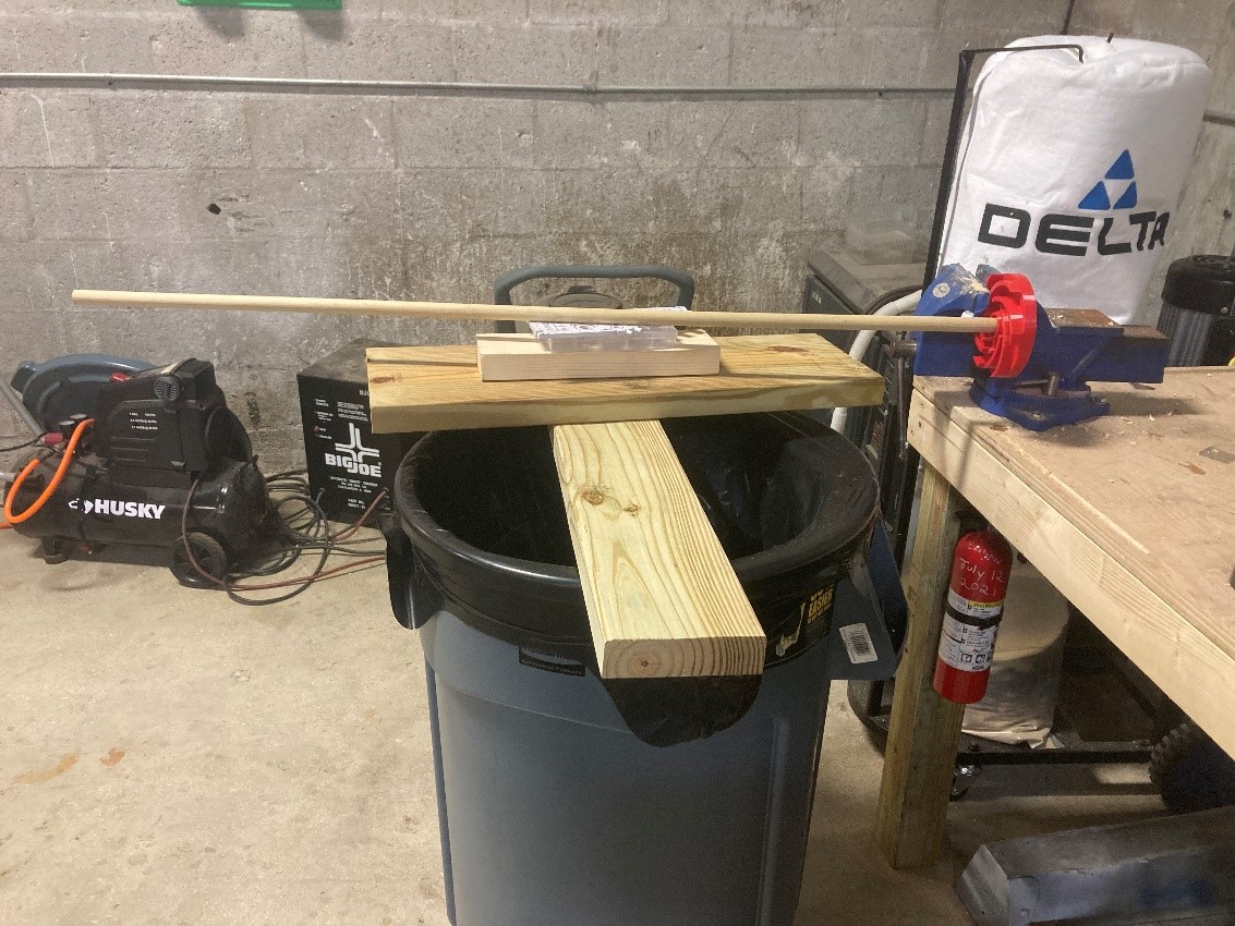
Unfortunately, due to the epoxy not being hardened, the turbine was unable to be used. Instead of attempting twice with the epoxy, Carmen and Tyler went back to Lowe’s and bought a dowel that perfectly fit the hole of the turbine. Tyler then hammered the dowel into the turbine, forcing it create a connected seal.

Tyler then built the turbine housing and mounting. The turbine housing was 3D printed and deemed a failure due to the mild interactions it had with the turbine. These interactions were slowing the turbine or causing it to stop spinning altogether.
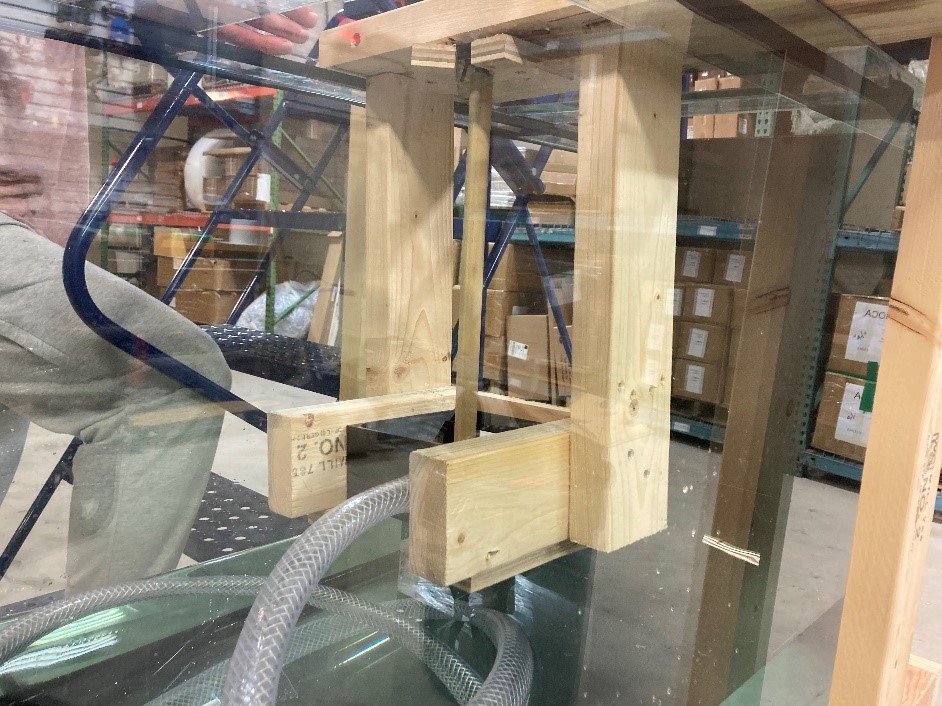
With the turbine housing disregarded, the turbine spun without constraints. However, the mounting needed to be designed and redesigned multiple times in order to ensure the proper rotation, lack of jostling of the dowel, and the securement of the turbine itself so that it would not fall into the water.
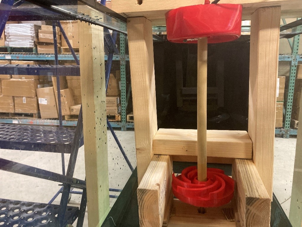
The Turbine mounting was designed, and in comparison to the initial set up seen above, the final design included the side pieces on either side of the turbine having been widened, a security plank of wood on the bottom of the turbine to prevent falling, and inside the red case on the top of the turbine lay the motor and all the wires necessary to transfer the converted electricity.
The initial design of the project included the powering of mini-LED’s lined up across the tank. However, the electricity generated was not enough to power the entire line up.
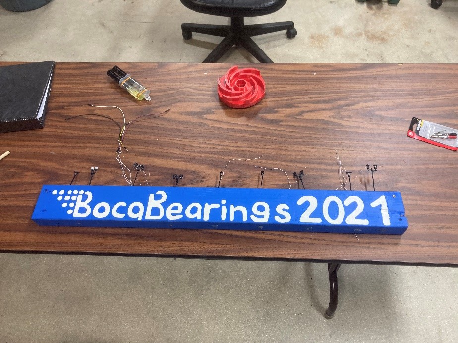
The LED’s required an initial power start up of 3V, which then requires mA of continuous voltage in order to stay on. This jump in power was too great for our system to generate, and therefore we were only able to power a single LED from our system.
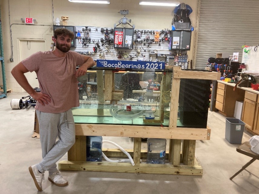
Although our system did not create the electricity needed for a complete fulfillment of the project proposal, we feel that this project does demonstrate the immense capacity needed to generate electricity. In such, we would like this project to help the community learn more about the process of work-to-energy systems and how this can impact public energy consumption.
See our video explanation here